Wednesday, December 3, 2025

SWP-B Universal Joint Shaft Coupling


SWP-B Universal Joint Shaft Coupling


文章附图

SWP-B Universal Joint Shaft Coupling


The SWP-B universal joint shaft coupling is a cross-shaft type universal joint coupling featuring a telescopic (lengadjustable) design. It is widely used in various types of heavy machinery.


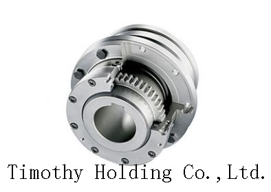
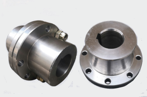
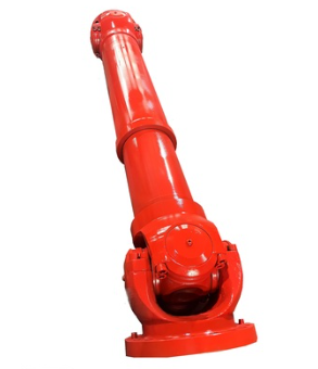
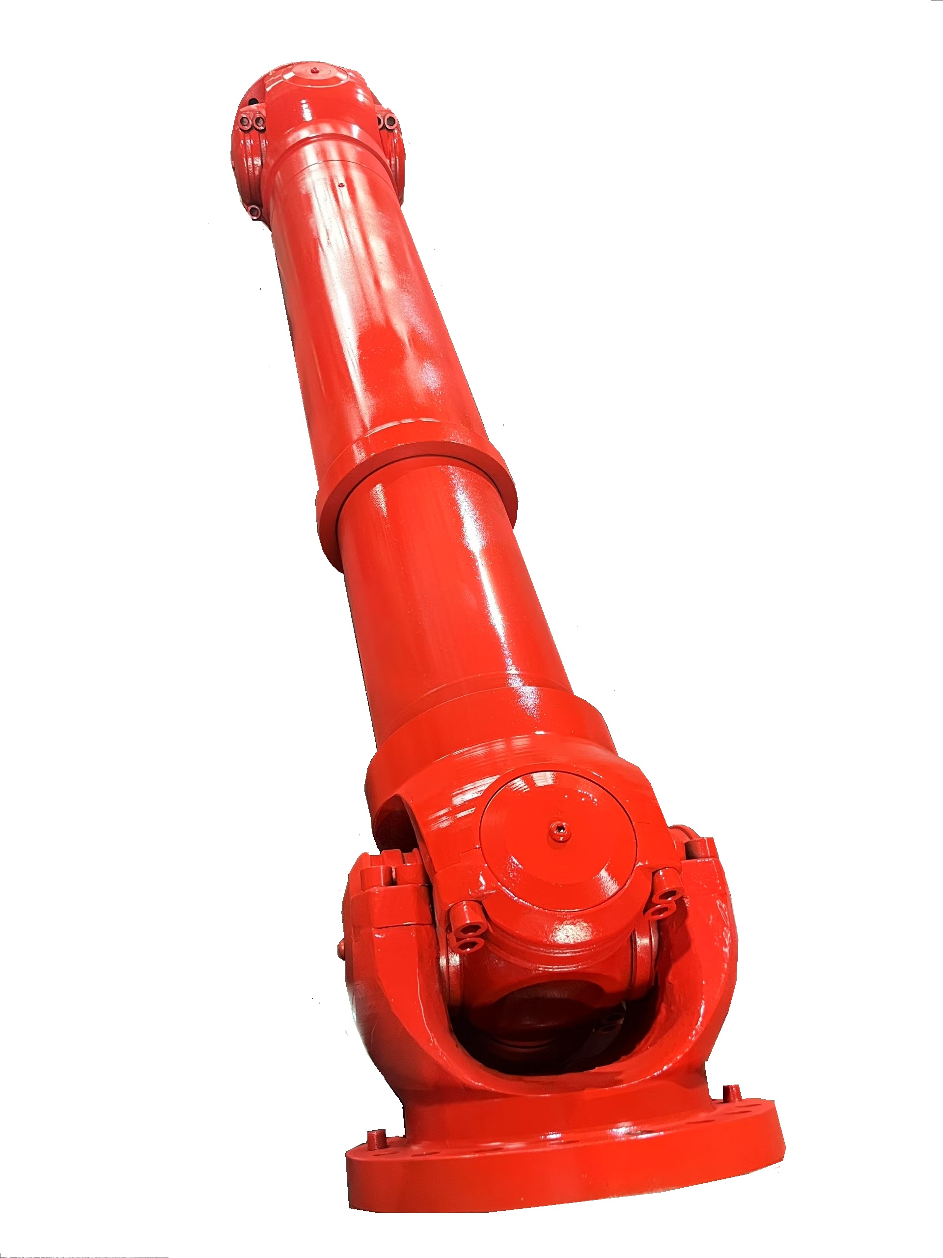
The SWP-B universal joint shaft is mainly composed of two universal joint yokes, a cross shaft, bearing housings, and other components. It boasts a compact structure and high transmission efficiency, enabling it to connect two transmission shaft systems with different axes, thereby achieving angle compensation and axis offset adjustment. Meanwhile, this coupling is also equipped with a telescopic function, allowing it to adapt to axial displacements within a certain range.


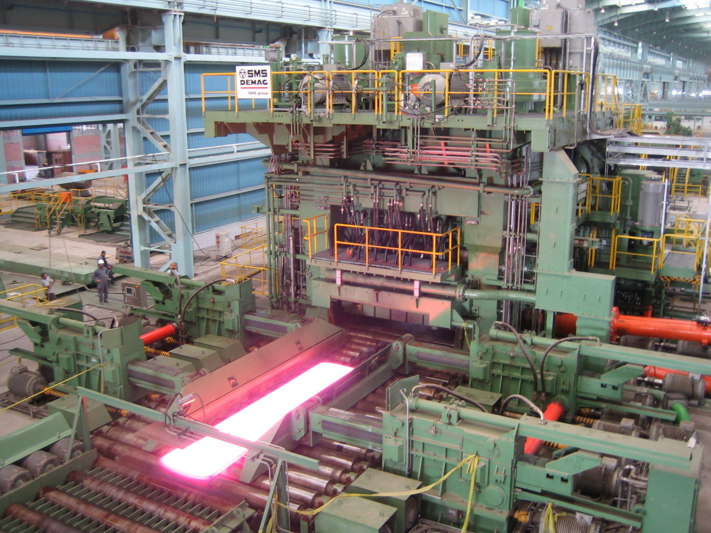
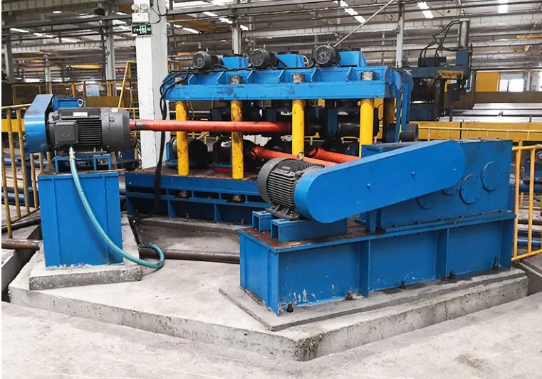
The SWP-B coupling is suitable for rolling machinery, lifting and transportation machinery, and other heavy machinery that requires connecting two transmission shaft systems with different axes.

When installing the SWP-B cross-shaft universal joint coupling, it is necessary to ensure the cleanliness of the flange joint surface and avoid impurities such as anti-rust grease. At the same time, the flange connection bolts must be tightened according to the specified tightening torque to ensure the stability and reliability of the coupling.

During the operation of the SWP-B cross-shaft universal joint coupling, long-term overloading should be avoided to prevent operational accidents.


During working operation, it is essential to frequently check the universal joint coupling for abnormal radial runout, bearing overheating, and other phenomena. Once such phenomena are detected, the machine should be shut down promptly for inspection and maintenance.


The SWP-B cross-shaft type universal joint coupling is a heavy machinery transmission component with a compact structure, high transmission efficiency, and a wide range of applications. During installation and maintenance, operations must be carried out strictly in accordance with regulations to ensure its normal operation and extend its service life.

Key Terminology Explanation (for clarity in engineering context)

swp universal joint shaft coupling.png

  • Universal joint coupling: A mechanical component used to transmit torque between two shafts that are not collinear (have misaligned axes).


  • Cross-shaft type: A common design of universal joint where a cross-shaped shaft (cross shaft) connects two yokes, enabling angular movement.


  • Telescopic function: The ability of the coupling to adjust its length, accommodating axial (along the shaft) displacements between connected shafts.


  • Tightening torque: The specific rotational force required to fasten bolts, ensuring secure assembly without damaging components (critical for mechanical stability).


Contact Name:August

Mobile Phone:+86-13758897904

E :august@timothyholding.com

Web:www.timothyholding.com

Address:55# Jinshi Road ,Lecheng Industrial Park,Yueqing City,Zhejiang provice,China

Tuesday, November 25, 2025

SWC225/250/285/315-BF Type Cardan Shaft


SWC225/250/285/315-BF Type Cardan Shaft

SWC225/250/285/315/350/390/440/550/620-BF Flange Type Cardan   Shafts


SWC225/250/285/315/350/390/440/550/620-BF Flange Type Cardan   Shafts

Product Features:

  1. Compact and reasonable structure. The SWC type adopts an integral yoke, making operation more reliable.

  2. Strong angular compensation capability. The axis deflection angle of the SWC type can reach 15-25 degrees.

  3. Stable operation, low noise, simple assembly, disassembly and maintenance, high transmission efficiency. It is suitable for high-power transmission, featuring energy saving, strong load-bearing capacity and high torque.

Product Material:

  • Regular material: 35CrMo and 20CrMnTi

  • Special customization available according to requirements

Cardan shaft is widely used in rolling mill, punch, straightener, crusher, ship drive, paper making equipment, common machinery, water pump equipment, test bench, and other mechanical applications.

Advantage:
1. Low life-cycle costs and long service life;
2. Increase productivity;
3. Professional and innovative solutions;
4. Reduce carbon dioxide emissions, and environmental protection;
5. High torque capacity even at large deflection angles;
6. Easy to move and run smoothly;

SWC225/250/285/315/350/390/440/550/620-BF Flange Type Cardan   Shafts


Contact Name:August

Mobile Phone:+86-13758897904

E :august@timothyholding.com

Web:www.timothyholding.com

Address:55# Jinshi Road ,Lecheng Industrial Park,Yueqing City,Zhejiang Province,China

Sunday, November 16, 2025

China Manufactuer of Cardan Shaft Universal Joint


cardan shaft universal joint 

China Manufactuer of Cardan Shaft Universal Joint


Performance Characteristics of Cardan Coupling

Cardan coupling is widely used in various industrial fields due to its excellent performance and characteristics. The following are the major performance characteristics of Cardan coupling:

  • High torque capacity

  • High misalignment tolerance

  • Smooth and vibration-free operation

  • Low maintenance requirements

  • High reliability and long service life

Types and Characteristics of Cardan Coupling

Cardan coupling can be divided into various types based on different classifications. The following are some common types and their characteristics:

  • Single joint Cardan coupling: Simple structure, suitable for small angle misalignment

  • Double joint Cardan coupling: Complex structure, suitable for large angle misalignment

  • Flange Cardan coupling: High torsional stiffness, suitable for high-precision equipment

  • Slip Cardan coupling: High misalignment tolerance, suitable for complex working conditions.

    cardan shaft universal coupling


Advantages of Different Materials for Cardan Coupling

The material of Cardan coupling is an important factor that affects its performance and service life. The following are the advantages of Cardan coupling made of different materials:

  • Steel Cardan coupling: High strength and durability, suitable for heavy-duty equipment

  • Aluminum Cardan coupling: Lightweight and corrosion-resistant, suitable for high-speed equipment

  • Stainless steel Cardan coupling: High corrosion resistance and hygiene, suitable for food and medical equipment

  • Titanium Cardan coupling: High temperature resistance and corrosion resistance, suitable for aerospace and military equipment

Contact Name:August

Mobile Phone:+86-13758897904

E :august@timothyholding.com

Web:www.timothyholding.com

Address:55# Jinshi Road ,Lecheng Industrial Park,Yueqing City,Zhejiang provice,China

Wednesday, August 6, 2025

Causes of Drum Gear Coupling Failures


Causes of Drum Gear Coupling Failures

文章附图

Causes of Drum Gear Coupling Failures

1. System Design & Integration Issues

· Unbalanced Shaft System Compatibility:
Components in the drive train (e.g., diesel engines, gearboxes, shafts, and highly elastic couplings) must be mutually complementary in design and application. Sub-optimal integration or low manufacturing precision in any component may compromise the entire system.

Example: In marine applications, improper alignment between the main engine and propulsion system accelerates coupling wear.

2. Mechanical Overload & Misalignment

· Damper Subsidence in Prime Movers:
Subsidence of the main engine's vibration damper induces shaft misalignment, generating additional torsional loads.

Consequence: Excessive heat buildup in highly elastic couplings leads to thermal stress fractures.

· Insufficient Compensation Capacity:
Despite their angular displacement tolerance, drum gear couplings may fail under unanticipated combined loads (e.g., simultaneous axial, radial, and angular stresses)sleeve.pngsleeves.png.

3. Operational & Maintenance Factors

· Improper Usage:

Overloading beyond rated torque.

Frequent starts/stops or reverse operations in non-design conditions.

· Environmental Neglect:

Contamination (dust, moisture) entering unsealed lubrication cavities.

Failure to replace degraded lubricant, accelerating tooth surface wear.

4. Industry-Specific Challenges

· Broad Application Scope:
Widely used in heavy industries (metallurgy, mining, etc.), couplings face diverse operational stresses.

Risk: Misapplication in high-speed or ultra-precision scenarios beyond their design limits.


Key Takeaway:
Drum gear coupling failures often stem from systematic design flawsmechanical over-stress, or operational oversights. Regular alignment checks, load monitoring, and adherence to lubrication protocols are critical for longevity.


https://www.timothyholding.com/Causes-of-Drum-Gear-Coupling-Failures.html


Monday, July 14, 2025

Application Scope of GICL & GIICL Series Drum Gear Couplings


Application Scope of GICL & GIICL Series Drum Gear Couplings

web:https://www.timothyholding.com:Timothy Couplings
文章附图

Application Scope of GICL & GIICL Series Drum Gear Couplings


1. Overview

Drum gear couplings (rigid flexible couplings) consist of internal gear rings and flanged half-couplings with external teeth, both sharing identical tooth counts. The external teeth are categorized as straight teeth or drum-shaped teeth. Compared to straight-tooth designs, drum-shaped teeth enable:

•Larger angular displacement tolerance

•Improved tooth contact conditions

•Enhanced torque transmission capacity

•Extended service life

GIICL drum gear coupling.jpg

 GICL & GIICL Series Drum Gear Couplings

2. Technical Features of GICL/GIICL Series

•Optimized for low-speed, heavy-load conditions

•Robust construction with high misalignment compensation (axial, radial, angular)

•Sealed lubrication system to minimize wear and ensure stable performance


3. Key Applications

GICL/GIICL series couplings are widely used in industries requiring reliable heavy-duty power transmission, including:

•Metallurgy: Rolling mills, blast furnace equipment

•Mining: Crushers, conveyors, hoisting systems

•Material Handling: Cranes, winches, heavy-duty transporters

•Petrochemical: Pumps, compressors, agitators

•General Machinery: High-torque drives in manufacturing and processing systems


4. Industry Advantages

•Durability: Designed to withstand harsh environments (shock loads, vibrations, temperature variations).

•Versatility: Suitable for both horizontal and vertical shaft configurations.

•Maintenance Efficiency: Modular design simplifies inspection and replacement.


https://www.timothyholding.com/Application-of-GICL-GIICL-Drum-Gear-Couplings.html


Monday, June 30, 2025

Differences Between Roller Chain Couplings and Gear Couplings


Differences Between Roller Chain Couplings and Gear Couplings

文章附图

Differences Between Roller Chain Couplings and Gear Couplings

1. Structural Differences

Roller Chain Coupling:

•Utilizes a double-row chain to simultaneously engage with two parallel sprockets (with identical tooth counts), connecting the two half-couplings.

Gear Coupling:

•Composed of two external gear hubs (with spherical-tooth-tip drum-shaped external teeth) and two internal gear sleeves (matching tooth count).

•The sleeves are key-connected to the shafts, while the hubs are bolted together.

•Sealed cavities store lubricating oil for enhanced durability.


2. Advantages

Roller Chain Coupling:

•Simple structure, compact size, lightweight.

•Easy installation, maintenance, and low cost.

•Moderate compensation capability and damping properties.

Gear Coupling:

•High torque transmission capacity.

•Effective compensation for combined displacements (axial, radial, angular).

shaft coupling.png
gear coupling

3. Disadvantages

Roller Chain Coupling:

•Unsuitable for reverse motion, frequent starts, vertical shaft transmission, or high-speed applications.

Gear Coupling:

•Bulky design and higher manufacturing cost.


4. Application Scope

Roller Chain Coupling:

•Ideal for low-speed, light-load applications (e.g., general machinery).

Gear Coupling:

•Designed for heavy-duty transmission scenarios (e.g., rolling mills, mining equipment).

•Precision-balanced variants can handle high-speed operations (e.g., steam turbine systems).


5. Technical Features

Gear Coupling (Drum Tooth Type):

•Drum-shaped teeth (arc profile) enable superior angular compensation compared to straight-tooth designs.

•Widely adopted in industries due to its robustness and adaptability.

Roller Chain Coupling:

•Simple assembly (4 components), no axial displacement required during disassembly.

•Operates reliably in harsh conditions (high temperature, humidity, dust).

•Limitations: Avoid shock loads in reverse motion; requires lubrication and protective housing.


6. Specifications (Roller Chain Coupling)

•13 standard sizes available.

•Shaft bore diameter: d = 16–190 mm

•Shaft bore length: L = 42–352 mm

•Rated torque: T = 40–25,000 N•m

•Permitted rotational speed [n]:

o200–1,400 rpm (without housing)

o900–4,500 rpm (with protective housing installed).


https://www.timothyholding.com/Roller-Chain-Couplings-and-Gear-Couplings.html