Showing posts with label shaft coupling. Show all posts

Wednesday, December 3, 2025

SWP-B Universal Joint Shaft Coupling
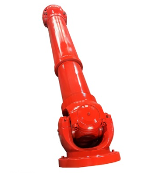
 

SWP-B Universal Joint Shaft Coupling


文章附图

SWP-B Universal Joint Shaft Coupling


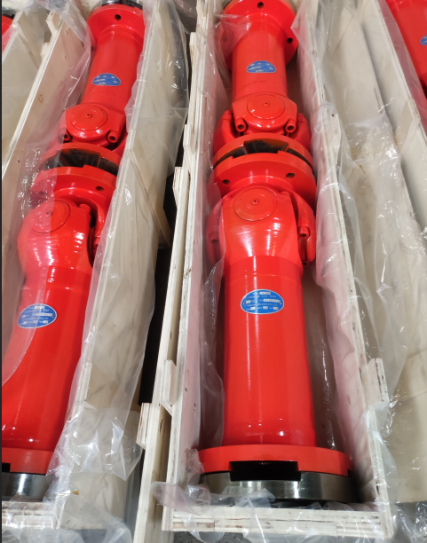
The SWP-B universal joint shaft coupling is a cross-shaft type universal joint coupling featuring a telescopic (lengadjustable) design. It is widely used in various types of heavy machinery.


The SWP-B universal joint shaft is mainly composed of two universal joint yokes, a cross shaft, bearing housings, and other components. It boasts a compact structure and high transmission efficiency, enabling it to connect two transmission shaft systems with different axes, thereby achieving angle compensation and axis offset adjustment. Meanwhile, this coupling is also equipped with a telescopic function, allowing it to adapt to axial displacements within a certain range.


The SWP-B coupling is suitable for rolling machinery, lifting and transportation machinery, and other heavy machinery that requires connecting two transmission shaft systems with different axes.

When installing the SWP-B cross-shaft universal joint coupling, it is necessary to ensure the cleanliness of the flange joint surface and avoid impurities such as anti-rust grease. At the same time, the flange connection bolts must be tightened according to the specified tightening torque to ensure the stability and reliability of the coupling.

During the operation of the SWP-B cross-shaft universal joint coupling, long-term overloading should be avoided to prevent operational accidents.


During working operation, it is essential to frequently check the universal joint coupling for abnormal radial runout, bearing overheating, and other phenomena. Once such phenomena are detected, the machine should be shut down promptly for inspection and maintenance.


The SWP-B cross-shaft type universal joint coupling is a heavy machinery transmission component with a compact structure, high transmission efficiency, and a wide range of applications. During installation and maintenance, operations must be carried out strictly in accordance with regulations to ensure its normal operation and extend its service life.

Key Terminology Explanation (for clarity in engineering context)

swp universal joint shaft coupling.png

  • Universal joint coupling: A mechanical component used to transmit torque between two shafts that are not collinear (have misaligned axes).


  • Cross-shaft type: A common design of universal joint where a cross-shaped shaft (cross shaft) connects two yokes, enabling angular movement.


  • Telescopic function: The ability of the coupling to adjust its length, accommodating axial (along the shaft) displacements between connected shafts.


  • Tightening torque: The specific rotational force required to fasten bolts, ensuring secure assembly without damaging components (critical for mechanical stability).


Contact Name:August

Mobile Phone:+86-13758897904

E :august@timothyholding.com

Web:www.timothyholding.com

Address:55# Jinshi Road ,Lecheng Industrial Park,Yueqing City,Zhejiang provice,China

Sunday, November 16, 2025

China Manufactuer of Cardan Shaft Universal Joint


cardan shaft universal joint 

China Manufactuer of Cardan Shaft Universal Joint


Performance Characteristics of Cardan Coupling

Cardan coupling is widely used in various industrial fields due to its excellent performance and characteristics. The following are the major performance characteristics of Cardan coupling:

  • High torque capacity

  • High misalignment tolerance

  • Smooth and vibration-free operation

  • Low maintenance requirements

  • High reliability and long service life

Types and Characteristics of Cardan Coupling

Cardan coupling can be divided into various types based on different classifications. The following are some common types and their characteristics:

  • Single joint Cardan coupling: Simple structure, suitable for small angle misalignment

  • Double joint Cardan coupling: Complex structure, suitable for large angle misalignment

  • Flange Cardan coupling: High torsional stiffness, suitable for high-precision equipment

  • Slip Cardan coupling: High misalignment tolerance, suitable for complex working conditions.

    cardan shaft universal coupling


Advantages of Different Materials for Cardan Coupling

The material of Cardan coupling is an important factor that affects its performance and service life. The following are the advantages of Cardan coupling made of different materials:

  • Steel Cardan coupling: High strength and durability, suitable for heavy-duty equipment

  • Aluminum Cardan coupling: Lightweight and corrosion-resistant, suitable for high-speed equipment

  • Stainless steel Cardan coupling: High corrosion resistance and hygiene, suitable for food and medical equipment

  • Titanium Cardan coupling: High temperature resistance and corrosion resistance, suitable for aerospace and military equipment

Contact Name:August

Mobile Phone:+86-13758897904

E :august@timothyholding.com

Web:www.timothyholding.com

Address:55# Jinshi Road ,Lecheng Industrial Park,Yueqing City,Zhejiang provice,China

Wednesday, August 6, 2025

Causes of Drum Gear Coupling Failures


Causes of Drum Gear Coupling Failures

文章附图

Causes of Drum Gear Coupling Failures

1. System Design & Integration Issues

· Unbalanced Shaft System Compatibility:
Components in the drive train (e.g., diesel engines, gearboxes, shafts, and highly elastic couplings) must be mutually complementary in design and application. Sub-optimal integration or low manufacturing precision in any component may compromise the entire system.

o Example: In marine applications, improper alignment between the main engine and propulsion system accelerates coupling wear.

2. Mechanical Overload & Misalignment

· Damper Subsidence in Prime Movers:
Subsidence of the main engine's vibration damper induces shaft misalignment, generating additional torsional loads.

o Consequence: Excessive heat buildup in highly elastic couplings leads to thermal stress fractures.

· Insufficient Compensation Capacity:
Despite their angular displacement tolerance, drum gear couplings may fail under unanticipated combined loads (e.g., simultaneous axial, radial, and angular stresses)sleeve.pngsleeves.png.

3. Operational & Maintenance Factors

· Improper Usage:

o Overloading beyond rated torque.

o Frequent starts/stops or reverse operations in non-design conditions.

· Environmental Neglect:

o Contamination (dust, moisture) entering unsealed lubrication cavities.

o Failure to replace degraded lubricant, accelerating tooth surface wear.

4. Industry-Specific Challenges

· Broad Application Scope:
Widely used in heavy industries (metallurgy, mining, etc.), couplings face diverse operational stresses.

o Risk: Misapplication in high-speed or ultra-precision scenarios beyond their design limits.


Key Takeaway:
Drum gear coupling failures often stem from systematic design flaws, mechanical over-stress, or operational oversights. Regular alignment checks, load monitoring, and adherence to lubrication protocols are critical for longevity.


https://www.timothyholding.com/Causes-of-Drum-Gear-Coupling-Failures.html


Friday, June 13, 2025

Lubrication Methods for Gear Couplings


Lubrication Methods for Gear Couplings

文章附图
drum gear coupling ,www.timothyholding.com

Lubrication Methods for Gear Couplings

Gear couplings are commonly used in heavy-duty industrial applications due to their high torque capacity and misalignment tolerance. Proper lubrication is critical to ensure smooth operation, minimize wear, and extend service life. There are three primary lubrication methods for gear couplings:

1. Reservoir Lubrication (Oil Bath or Grease Packing)

Characteristics:

· Lubricant is injected through a nozzle and retained inside the coupling due to centrifugal force.

· Forms a lubricating film on the gear teeth but allows contaminants to accumulate inside.

· Poor heat dissipation due to limited oil flow.

Applications:

· Suitable for low-speed, low-power applications.

· Grease-packed variant: Sealed with lubricant inside, requiring periodic cleaning and re-greasing.

Maintenance Requirements:

· Regularly check lubricant condition.

· Replace grease or oil during scheduled maintenance.

2. Continuous Flow Lubrication (Drip or Splash Lubrication)

Characteristics:

· Oil is injected through a nozzle and flows through gear side clearances before draining out via small holes in the sleeve.

· Primarily provides cooling rather than forming a strong lubricating film.

· Faster tooth wear compared to forced lubrication.

Applications:

· Used in moderate-speed applications where cooling is prioritized over extreme load capacity.

Maintenance Requirements:

· Ensure consistent oil flow to prevent overheating.

· Monitor oil quality to avoid contamination buildup.

3. Forced Lubrication (Jet or Spray Lubrication)

Characteristics:

· Oil is pressurized and injected through small holes at the base of the gear teeth.

· Centrifugal force drives oil into the meshing surfaces for optimal lubrication & cooling.

· Contaminants are flushed out continuously, improving cleanliness.

Applications:

· Ideal for high-speed, high-load applications (e.g., turbines, compressors, heavy machinery).

Maintenance Requirements:

· Use high-quality, high-viscosity lubricants.

· Ensure proper oil pressure and flow rate.

· Regularly inspect filtration systems to prevent clogging.

Comparison of Lubrication Methods

Method

Advantages

Disadvantages

Best For

Reservoir Lubrication

Simple, low maintenance

Poor cooling, contaminant buildup

Low-speed, light-duty

Continuous Flow

Better cooling than reservoir

Weak oil film, faster wear

Moderate-speed applications

Forced Lubrication

Best cooling & lubrication, clean

Complex system, higher maintenance

High-speed, heavy-duty

Best Practices for Gear Coupling Lubrication

✔ Select the right lubricant (oil viscosity / grease type) based on speed and load.
✔ Follow manufacturer’s guidelines for lubrication intervals.
✔ Monitor oil/grease condition to prevent contamination and degradation.
✔ Inspect seals to avoid leaks in forced lubrication systems.

By choosing the appropriate lubrication method and maintaining it properly, gear couplings can achieve longer service life, reduced downtime, and improved efficiency.

crane drum gear coupling.png
drum gear coupling ,www.timothyholding.com

https://www.timothyholding.com/Lubrication-Methods-for-Gear-Couplings.html

Wednesday, June 11, 2025

Coupling Manufacturing Process


文章附图
shaft coupling ,www.timothyholding.com

Coupling Manufacturing Process

Couplings fall under the category ofgeneral mechanical components, used to connect two shafts (drive shaft and driven shaft) in a mechanical system, transmitting torque through rotation. Inhigh-speed, heavy-duty power transmission, some couplings also providebuffering, vibration damping, and improved dynamic performance of the shaftsystem.

SWP cardan shaft.png
universal joint coupling ,www.timothyholding.com

A coupling consists of a cold-assembled section that connects the driveand driven shafts.

In shaft-driven mechanical systems,couplings are commonly used as connecting elements. Most power machinery islinked to working machines via couplings. By the late 20th century, couplingproducts had rapidly developed both domestically and internationally. For mostdesigners, selecting the right coupling to meet machine requirements fromvarious options with different performance characteristics has always been achallenge in product design.

Common types of couplings include:

  • Plum     blossom (jaw) couplings

  • Diaphragm     couplings

  • Oldham     (cross-slider) couplings

  • Gear     couplings

  • Universal     joints

  • Star-shaped     elastic couplings

  • Flexible     (elastomeric) couplings


Forging Process

Forging can be categorized into manualfree forging and mechanical free forging.

  • Manual free forging has low     production efficiency and high labor intensity, making it suitable only     for repairs or small-scale, simple production.

  • In     modern industrial production, mechanical free forging has     become the primary method, playing a crucial role in heavy machinery     manufacturing.

Material Requirements for Coupling Forgings:

  • Must     come with inspection certificates.

  • Material     substitution requires buyer approval and written documentation.

  • Forgings     must be produced using hydraulic presses or sufficiently powered forging     hammers.

  • Adequate     forging ratios must be maintained to ensure uniform microstructure.

  • The     forging axis should align with the ingot’s central axis.

  • Forgings     can be made from ingots or billets; scale forging is permitted but     requires separate heat treatment.


WZL Standard Crane Drum Coupling

Post-Forging Heat Treatment

  • Pre-heat treatment is     performed to refine the forging’s microstructure and improve     machinability.

Rough Machining

  • Before     heat treatment, rough machining is conducted, leaving minimal machining     allowance.

Performance Heat Treatment

  • Quenching and tempering are     applied to achieve required mechanical properties.

Post-Treatment Machining

  • After     passing mechanical property tests, forgings are machined to dimensions and     surface roughness specified in supplier drawings.

  • If any     surface exceeds rework limits, stress relief is mandatory.

Stress Relief Treatment

  • Stress     relief temperature must be 30°C below final tempering temperature,     followed by slow cooling.

  • If     stress relief exceeds this limit, mechanical retesting is required.