Showing posts with label cardan shaft coupling. Show all posts

Wednesday, June 11, 2025

Coupling Manufacturing Process


文章附图
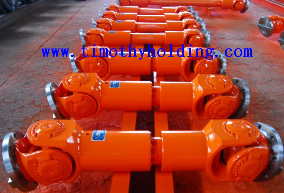
shaft coupling ,www.timothyholding.com

Coupling Manufacturing Process

Couplings fall under the category ofgeneral mechanical components, used to connect two shafts (drive shaft and driven shaft) in a mechanical system, transmitting torque through rotation. Inhigh-speed, heavy-duty power transmission, some couplings also providebuffering, vibration damping, and improved dynamic performance of the shaftsystem.

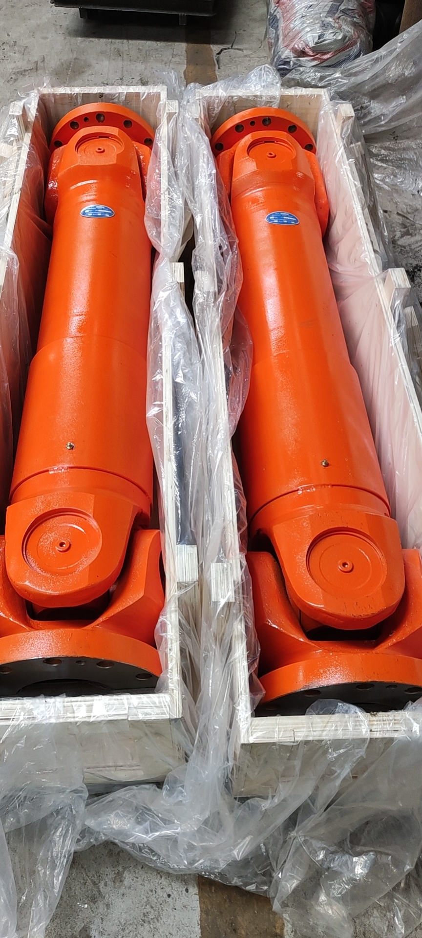
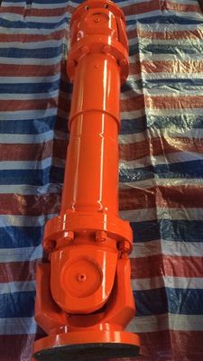
SWP cardan shaft.png
universal joint coupling ,www.timothyholding.com

A coupling consists of a cold-assembled section that connects the driveand driven shafts.

In shaft-driven mechanical systems,couplings are commonly used as connecting elements. Most power machinery islinked to working machines via couplings. By the late 20th century, couplingproducts had rapidly developed both domestically and internationally. For mostdesigners, selecting the right coupling to meet machine requirements fromvarious options with different performance characteristics has always been achallenge in product design.

Common types of couplings include:

  • Plum     blossom (jaw) couplings

  • Diaphragm     couplings

  • Oldham     (cross-slider) couplings

  • Gear     couplings

  • Universal     joints

  • Star-shaped     elastic couplings

  • Flexible     (elastomeric) couplings


Forging Process

Forging can be categorized into manualfree forging and mechanical free forging.

  • Manual free forging has low     production efficiency and high labor intensity, making it suitable only     for repairs or small-scale, simple production.

  • In     modern industrial production, mechanical free forging has     become the primary method, playing a crucial role in heavy machinery     manufacturing.

Material Requirements for Coupling Forgings:

  • Must     come with inspection certificates.

  • Material     substitution requires buyer approval and written documentation.

  • Forgings     must be produced using hydraulic presses or sufficiently powered forging     hammers.

  • Adequate     forging ratios must be maintained to ensure uniform microstructure.

  • The     forging axis should align with the ingot’s central axis.

  • Forgings     can be made from ingots or billets; scale forging is permitted but     requires separate heat treatment.


WZL Standard Crane Drum Coupling

Post-Forging Heat Treatment

  • Pre-heat treatment is     performed to refine the forging’s microstructure and improve     machinability.

Rough Machining

  • Before     heat treatment, rough machining is conducted, leaving minimal machining     allowance.

Performance Heat Treatment

  • Quenching and tempering are     applied to achieve required mechanical properties.

Post-Treatment Machining

  • After     passing mechanical property tests, forgings are machined to dimensions and     surface roughness specified in supplier drawings.

  • If any     surface exceeds rework limits, stress relief is mandatory.

Stress Relief Treatment

  • Stress     relief temperature must be 30°C below final tempering temperature,     followed by slow cooling.

  • If     stress relief exceeds this limit, mechanical retesting is required.

Monday, June 9, 2025

The processing steps for drum gear couplings


The processing steps for drum gear couplings

文章附图

What are the processing steps for drum gear couplings ?
Drum gear couplings are generally processed through turning and milling operations (CNC milling ensures higher precision). Keyways can be machined via wire cutting or broaching.

Processing Methods:
Typical manufacturing steps include turning, milling, gear hobbing, and gear shaping. The tooth surfaces undergo high-frequency quenching. For higher performance requirements, die forging is used to shape the coupling before machining. Some couplings are formed using cast steel or cast iron, followed by machining.

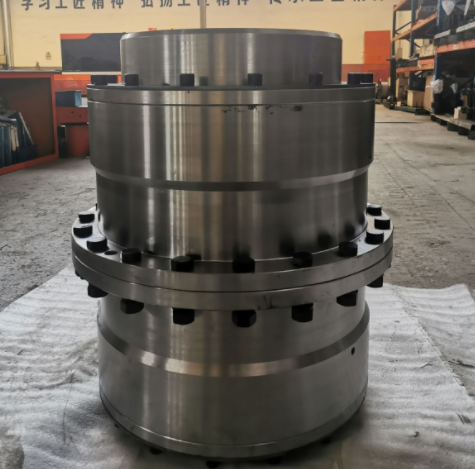
drum gear coupling for crane.png

Technical Overview:
Drum gear couplings fall under the category of flexible-rigid couplings. They consist of internal gear rings and flanged half-couplings with external teeth. The external teeth are either straight or drum-shaped. Compared to straight-tooth couplings, drum-shaped teeth allow for greater angular displacement, improve tooth contact conditions, enhance torque transmission capacity, and extend service life.

Key Advantages:

1. High Load Capacity: The carburizing and quenching treatment of the drum-shaped tooth surfaces significantly increases load-bearing capacity.

2. Reduced Wear: When forced oil lubrication is applied, tooth surface wear decreases dramatically (to approximately 10% of that with grease lubrication). Circulating oil also dissipates heat generated by rolling mills and gear friction, preventing degradation of the material’s allowable contact stress.

3. Durability: Under normal conditions, tooth breakage is avoided, meeting the demands of continuous rolling mill operations.

4. Axial Flexibility: The design accommodates axial displacement during rolling mill operation, enabling easy expansion and contraction.

5. Operational Benefits: Safe, clean, and efficient performance.


https://www.timothyholding.com/The-processing-steps-for-drum-gear-couplings.html

Wednesday, June 4, 2025

Application and Considerations for Couplings in Rolling Mills


Application and Considerations for Couplings in Rolling Mills

Timothy Cardan Shafts
文章附图

Application and Considerations for Couplings in Rolling Mills

1. Application of Couplings in Rolling Mills

Couplings are critical transmissioncomponents in rolling mills, connecting the motor, reducer, and work rolls totransmit torque and accommodate misalignment. The most commonly used typesinclude:

  • Gear Couplings: Widely     adopted due to their high torque capacity (standardized for <1000 kN·m     in China) and ability to handle slight angular/radial deviations.

  • Elastic Sleeve Pin Couplings: Used in some mills for their compact size and heavy-load     capability, suitable for low-speed, high-torque applications. However,     they are being phased out and should be avoided in new designs.

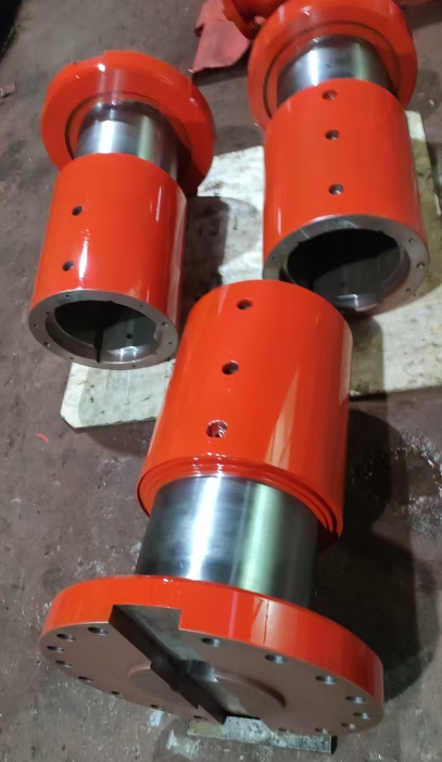
    sleeves.png

2. Key Considerations

  • Axial Load Resistance: Gear     couplings in rolling mills often endure heavy axial loads, which may shear     the sealing end cover screws, damage seals (causing oil leaks), and     accelerate gear wear. Solution: Increase screw diameter in     heavy-duty designs.

  • Precision & Balancing: For high-speed applications (e.g., roll shafts), couplings must be     dynamically balanced to minimize vibration.

  • Obsolescence Risk: Avoid     outdated designs like elastic sleeve pin couplings unless necessary for     legacy systems.

3. System Integration

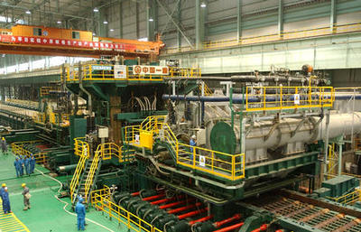
Rolling mills consist of a prime mover(motor), transmission (couplings, gearboxes), and actuators (rolls). Propercoupling selection ensures efficient power transfer, reduces downtime, andextends equipment life.

Note: Regular maintenance (e.g., lubrication, sealinspection) is essential to prevent failures in harsh rolling mill conditions.


Translation Rationale:

  • Structure: Organized     into clear sections for technical readability.

  • Terminology: Uses     industry-standard terms (e.g., "dynamic balancing,"     "angular/radial deviations").

  • Conciseness: Combines     related ideas (e.g., axial load effects + solutions) for efficiency.

  • Warnings: Explicitly     flags phased-out components to align with the original text’s intent.

https://www.timothyholding.com/Application-of-Couplings-in-Rolling-Mills.html

Wednesday, March 27, 2024

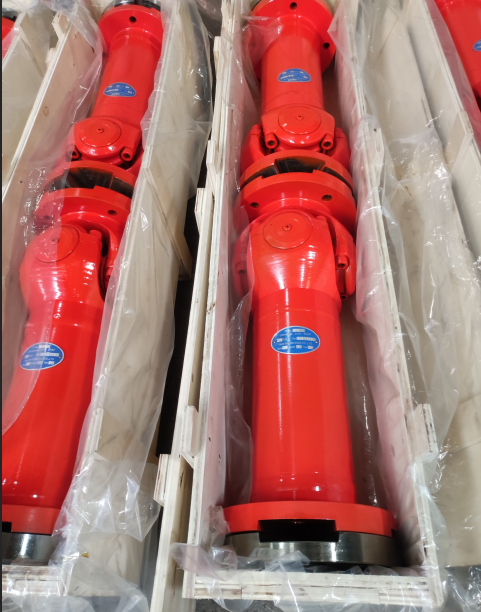
Cardan Shafts For Steekle Mill


Cardan Shafts For Steekle Mill

Cardan Shafts For Steekle Mill


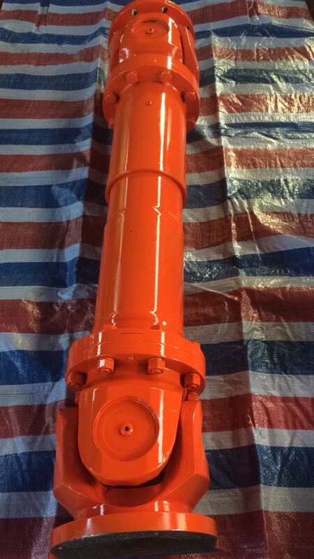
Industrial drive shafts used in Steckel mill


Material:35CrMo and 20CrMnTi

Cardan shaft.jpg

Largely used in rolling mill,steel mill,paper mill ,ladle crane ,mining machinery and other heavy duty machinery


Industrial cardan drive shafts

Industrial cardan shafts


Timothy Holding Co.,Ltd

Contact Name:August

Mobile Phone:+86–13758897904

E :august@timothyholding.com

http://www.timothyholding.com

Tuesday, May 31, 2016

SWC- CH cardan drive shaft

SWC- CH cardan drive shaft
产品详情

Material:35CrMo and 20CrMnTi

Largely used in rolling mills,Pipe straighteners,Steel mill,tube mill,Continuous casting machinery,Paper machines ,Piercing mills,Bridge cranes,Steckel mill,Punchers,Roller conveyor, Rotating furnace,Mining machinery and other heavy duty machinery .
http://www.timothyholding.com/pd.jsp?id=53&_pp=0_304_2_-1

Tuesday, April 19, 2016

SWP-D cardan drive shaft

SWP-D cardan drive shaft
产品详情
SWP-D cardan drive shaft

Material:35CrMo and 20CrMnTi

Largely used in rolling mills,Pipe straighteners,Steel mill,tube mill,Continuous casting machinery,Paper machines ,Piercing mills,Bridge cranes,Steckel mill,Punchers,Roller conveyor, Rotating furnace,Mining machinery and other heavy duty machinery .

http://www.timothyholding.com/pd.jsp?id=57&_pp=0_304_1_-1

Thursday, April 14, 2016

SWP-A cardan drive shaft

SWP-A cardan drive shaft
产品详情
Universal joint shaft/Industrial cardan drive shaft

Material:35CrMo and 20CrMnTi

Largely used in rolling mills,Pipe straighteners,Steel mill,tube mill,Continuous casting machinery,Paper machines ,Piercing mills,Bridge cranes,Steckel mill,Punchers,Roller conveyor, Rotating furnace,Mining machinery and other heavy duty machinery.
http://www.timothyholding.com/pd.jsp?id=55&_pp=0_304_1_-1