Showing posts with label universal joint coupling. Show all posts

Sunday, January 18, 2026

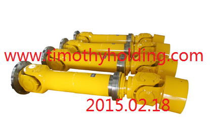
Universal Joint Couplings as Critical Mechanical Transmission Components
 

Universal Joint Couplings as Critical Mechanical Transmission Components

文章附图

Universal Joint Couplings as Critical Mechanical Transmission Components

Fundamental Role in Power Transmission

Universal joint couplings serve asessential components in mechanical power transmission systems, widely employedin:

  • Automotive     systems

  • Lifting     and transportation equipment

  • Construction     machinery

  • Industrial     machinery

    Universal joint couplings.png

Common Types of Constant Velocity Joints

  1. Rzeppa (Ball-type) Joints

  2. Double Cardan Joints

  3. Cross-slider Couplings

  4. Disc-type Couplings

These are particularly suitable forconnecting:

  • Intersecting     shafts

  • Parallel     shafts

  • Providing     constant velocity transmission

Advanced Spatial Mechanism Applications

Recent research has developed specializeduniversal joint designs for:

  • Direct     connection of spatial intersecting shafts

  • Large-angle     intersecting shaft connections (with wide variable range)

  • Simplified     manufacturing with fewer components

Critical Application Case: Tube RollingMills

In rolling mill main drive systemsconsisting of:

  • Main     motor

  • Reducer

  • Connecting     shaft

  • Universal     joint coupling

The universal joint coupling represents themost vulnerable mechanical component, where traditional design approaches facedlimitations:

Traditional Design Limitations

  1. Engineering Mechanics     Methods

    • Limited accuracy

    • Poor reliability

  2. Empirical Formula Methods

    • Based on experimental data

    • Required large safety factors

    • Resulted in oversizing and higher costs

Modern Computational Analysis Advancements

With computer technology development,numerical analysis methods have revolutionized design:

Finite Element Method (FEM) Advantages

  • Powerful     computational mathematics approach

  • Widely     adopted in metallurgical equipment design

  • Particularly     effective for complex components like universal joints

  • Provides     practical, reliable and convenient analysis

Modeling Optimization Techniques

Key simplifications in FEM modeling:

  1. Focus on Critical     Components

    • Primarily analyzing the yoke head

    • Simplified modeling of roll-end components

  2. Contact Simulation

    • Independent modeling of:

      • Yoke

      • Jaw

      • Roll-end flange

    • Creation of contact pairs to simulate force transmission

  3. Reasonable Simplifications

    • Ignoring non-load-bearing bolts

    • Omitting minor fillets and rounds

    • Eliminating rigid body displacement

Performance Enhancement Strategies

  1. Precision Manufacturing

    • Improved component geometry

    • Enhanced surface finishes

  2. Material Optimization

    • Advanced alloy selection

    • Heat treatment processes

  3. Maintenance Considerations

    • Lubrication system design

    • Wear monitoring techniques


  4. Timothy Holding Co.,Ltd.

    Sales Manager

    Mobile:+86-13758897904(August.Zeng)

    Sales Email: august@timothyholding.com

                       timothyholding@163.com


    http://www.timothyholding.com


    Add:55# Jinshi Road,Lecheng   Industrial Part,Yueqing City,Zhejiang Province,China

https://www.timothyholding.com/Universal-Joint-Couplings-Transmission-Components.html

Wednesday, June 11, 2025

Coupling Manufacturing Process


文章附图
shaft coupling ,www.timothyholding.com

Coupling Manufacturing Process

Couplings fall under the category ofgeneral mechanical components, used to connect two shafts (drive shaft and driven shaft) in a mechanical system, transmitting torque through rotation. Inhigh-speed, heavy-duty power transmission, some couplings also providebuffering, vibration damping, and improved dynamic performance of the shaftsystem.

SWP cardan shaft.png
universal joint coupling ,www.timothyholding.com

A coupling consists of a cold-assembled section that connects the driveand driven shafts.

In shaft-driven mechanical systems,couplings are commonly used as connecting elements. Most power machinery islinked to working machines via couplings. By the late 20th century, couplingproducts had rapidly developed both domestically and internationally. For mostdesigners, selecting the right coupling to meet machine requirements fromvarious options with different performance characteristics has always been achallenge in product design.

Common types of couplings include:

  • Plum     blossom (jaw) couplings

  • Diaphragm     couplings

  • Oldham     (cross-slider) couplings

  • Gear     couplings

  • Universal     joints

  • Star-shaped     elastic couplings

  • Flexible     (elastomeric) couplings


Forging Process

Forging can be categorized into manualfree forging and mechanical free forging.

  • Manual free forging has low     production efficiency and high labor intensity, making it suitable only     for repairs or small-scale, simple production.

  • In     modern industrial production, mechanical free forging has     become the primary method, playing a crucial role in heavy machinery     manufacturing.

Material Requirements for Coupling Forgings:

  • Must     come with inspection certificates.

  • Material     substitution requires buyer approval and written documentation.

  • Forgings     must be produced using hydraulic presses or sufficiently powered forging     hammers.

  • Adequate     forging ratios must be maintained to ensure uniform microstructure.

  • The     forging axis should align with the ingot’s central axis.

  • Forgings     can be made from ingots or billets; scale forging is permitted but     requires separate heat treatment.


WZL Standard Crane Drum Coupling

Post-Forging Heat Treatment

  • Pre-heat treatment is     performed to refine the forging’s microstructure and improve     machinability.

Rough Machining

  • Before     heat treatment, rough machining is conducted, leaving minimal machining     allowance.

Performance Heat Treatment

  • Quenching and tempering are     applied to achieve required mechanical properties.

Post-Treatment Machining

  • After     passing mechanical property tests, forgings are machined to dimensions and     surface roughness specified in supplier drawings.

  • If any     surface exceeds rework limits, stress relief is mandatory.

Stress Relief Treatment

  • Stress     relief temperature must be 30°C below final tempering temperature,     followed by slow cooling.

  • If     stress relief exceeds this limit, mechanical retesting is required.

Wednesday, May 21, 2025

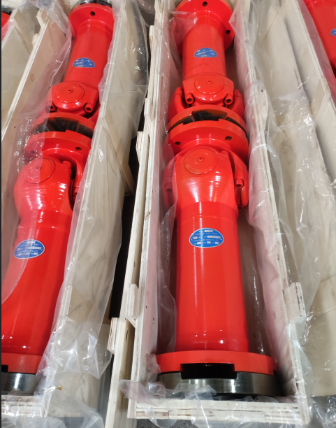
Universal Joint Couplings as Critical Mechanical Transmission Components


Universal Joint Couplings as Critical Mechanical Transmission Components

来源:https://www.timothyholding.com作者:Timoghy Cardan Shaft网址:https://www.timothyholding.com/Universal-Joint-Couplings-Transmission-Components.html
文章附图

Universal Joint Couplings as Critical Mechanical Transmission Components

Fundamental Role in Power Transmission

Universal joint couplings serve asessential components in mechanical power transmission systems, widely employedin:

  • Automotive     systems

  • Lifting     and transportation equipment

  • Construction     machinery

  • Industrial     machinery

    Universal joint couplings.png

Common Types of Constant Velocity Joints

  1. Rzeppa (Ball-type) Joints

  2. Double Cardan Joints

  3. Cross-slider Couplings

  4. Disc-type Couplings

These are particularly suitable forconnecting:

  • Intersecting     shafts

  • Parallel     shafts

  • Providing     constant velocity transmission

Advanced Spatial Mechanism Applications

Recent research has developed specializeduniversal joint designs for:

  • Direct     connection of spatial intersecting shafts

  • Large-angle     intersecting shaft connections (with wide variable range)

  • Simplified     manufacturing with fewer components

Critical Application Case: Tube RollingMills

In rolling mill main drive systemsconsisting of:

  • Main     motor

  • Reducer

  • Connecting     shaft

  • Universal     joint coupling

The universal joint coupling represents themost vulnerable mechanical component, where traditional design approaches facedlimitations:

Traditional Design Limitations

  1. Engineering Mechanics     Methods

    • Limited accuracy

    • Poor reliability

  2. Empirical Formula Methods

    • Based on experimental data

    • Required large safety factors

    • Resulted in oversizing and higher costs

Modern Computational Analysis Advancements

With computer technology development,numerical analysis methods have revolutionized design:

Finite Element Method (FEM) Advantages

  • Powerful     computational mathematics approach

  • Widely     adopted in metallurgical equipment design

  • Particularly     effective for complex components like universal joints

  • Provides     practical, reliable and convenient analysis

Modeling Optimization Techniques

Key simplifications in FEM modeling:

  1. Focus on Critical     Components

    • Primarily analyzing the yoke head

    • Simplified modeling of roll-end components

  2. Contact Simulation

    • Independent modeling of:

      • Yoke

      • Jaw

      • Roll-end flange

    • Creation of contact pairs to simulate force transmission

  3. Reasonable Simplifications

    • Ignoring non-load-bearing bolts

    • Omitting minor fillets and rounds

    • Eliminating rigid body displacement

Performance Enhancement Strategies

  1. Precision Manufacturing

    • Improved component geometry

    • Enhanced surface finishes

  2. Material Optimization

    • Advanced alloy selection

    • Heat treatment processes

  3. Maintenance Considerations

    • Lubrication system design

    • Wear monitoring techniques


https://www.timothyholding.com/Universal-Joint-Couplings-Transmission-Components.html

Thursday, July 28, 2016

Universal drive shafts

Universal drive shafts
产品详情

Material:35CrMo and 20CrMnTi

Largely used in rolling mills,Pipe straighteners,Steel mill,tube mill,Continuous casting machinery,Paper machines ,Piercing mills,Bridge cranes,Steckel mill,Punchers,Roller conveyor, Rotating furnace,Mining machinery and other heavy duty machinery .


Thursday, July 7, 2016

SWC250 Universal joint shaft

SWC250  Universal joint shaft
产品详情
SWC250  Universal joint shaft

Material:35CrMo and 20CrMnTi

Largely used in rolling mills,Pipe straighteners,Steel mill,tube mill,Continuous casting machinery,Paper machines ,Piercing mills,Bridge cranes,Steckel mill,Punchers,Roller conveyor, Rotating furnace,Mining machinery and other heavy duty machinery .

http://www.timothyholding.com/pd.jsp?id=11&_pp=0_304_2_-1


Piercing mill
SWP series cardan shaft

Tuesday, April 12, 2016

SWP universal joint shaft

SWP universal joint shaft
产品详情
Universal joint shaft/Industrial cardan drive shaft

Material:35CrMo and 20CrMnTi

Largely used in rolling mills,Pipe straighteners,Steel mill,tube mill,Continuous casting machinery,Paper machines ,Piercing mills,Bridge cranes,Steckel mill,Punchers,Roller conveyor, Rotating furnace,Mining machinery and other heavy duty machinery .
http://www.timothyholding.com/pd.jsp?id=56&_pp=0_304_1_-1