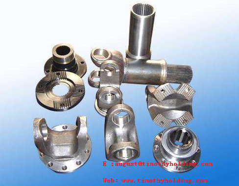
A drive shaft consists of a shaft tube, a telescopic sleeve, and a universal joint.
The Drive Shaft is a circular component that connects or assembles various parts, while being capable of moving or rotating. It is generally made of lightweight alloy steel tubes with excellent torsional resistance. For front-engine, rear-wheel-drive vehicles, it is the shaft that transmits the rotation of the transmission to the final drive. It can consist of multiple sections connected by universal joints. As a high-speed rotating body with minimal support, its dynamic balance is crucial. Typically, drive shafts undergo dynamic balance testing before leaving the factory and are adjusted on a balancing machine.
The drive shaft is a key component for transmitting power in a vehicle's drive train. Its function, together with the gearbox and drive axle, is to transfer power from the engine to the wheels, enabling the vehicle to generate driving force.
Special vehicle drive shafts are mainly used in models such as oil tankers, refueling trucks, sprinkler trucks, sewage suction trucks, fecal suction trucks, fire trucks, high-pressure cleaning trucks, road wreckers, aerial work platforms, and garbage trucks.
The universal joint is a critical component of a vehicle's drive shaft. A vehicle is a moving object. In rear-wheel-drive vehicles, the engine, clutch, and transmission are mounted as a single unit on the frame, while the drive axle is connected to the frame via elastic suspension. There is a distance between these two assemblies, which requires a connection. During vehicle operation, uneven road surfaces cause jolting.
 |
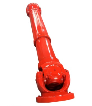
| Heavy-duty Vehicle Drive Shaft,www.timothyholding.com |
A typical universal joint is composed of a cross shaft, cross bearings, and a flange yoke. It is a key component of the vehicle's drive shaft. In front-engine, rear-wheel-drive vehicles, the universal joint drive shaft is installed between the transmission output shaft and the drive axle final drive input shaft. In front-engine, front-wheel-drive vehicles, the drive shaft is omitted, and universal joints are installed between the front axle half-shafts (which are responsible for both driving and steering) and the wheels. During vehicle operation, uneven road surfaces cause jolting, load changes, or differences in the installation positions of the two assemblies—all of which can alter the angle and distance between the transmission output shaft and the drive axle final drive input shaft. Therefore, a device that "adapts to changes" is needed to solve this problem, leading to the development of the universal joint.
In front-engine, rear-wheel-drive (or all-wheel-drive) vehicles, suspension deformation during movement causes frequent relative motion between the drive axle final drive input shaft and the transmission (or transfer case) output shaft. Additionally, to avoid certain mechanisms or devices (making linear power transmission impossible), a device is necessary to ensure normal power transmission—hence the emergence of universal joint transmission. Universal joint transmission must meet the following characteristics:
a. Reliably transmit power when the relative position of the two connected shafts changes within the expected range;
b. Ensure uniform operation of the two connected shafts. The additional load, vibration, and noise caused by the universal joint angle must be within allowable limits;
c. High transmission efficiency, long service life, simple structure, easy manufacturing, and convenient maintenance. For vehicles, since the output shaft of a single cross-shaft universal joint rotates at a non-uniform speed relative to the input shaft (when there is a certain angle), a double universal joint (or multi-universal joint) transmission must be used. The two universal joint yokes connected to the same drive shaft should be arranged in the same plane, and the angles of the two universal joints should be equal. This is extremely important. During design, the angle of the universal joint should be minimized as much as possible.
Telescopic Sleeve
In the traditional drive shaft structure, the spline sleeve is welded to the flange yoke, and the spline shaft is welded to the drive shaft tube. The new-type drive shaft abandons this traditional structure: instead, the spline sleeve is welded integrally with the drive shaft tube, and the spline shaft is made integrally with the flange yoke. Furthermore, the rectangular-tooth spline is replaced with a large-pressure-angle involute short-tooth spline, which not only enhances strength but also facilitates extrusion forming, meeting the requirements of high-torque working conditions. The tooth surfaces of the telescopic sleeve and spline shaft are fully coated with a layer of nylon material, which not only improves wear resistance and self-lubrication but also reduces damage to the drive shaft caused by impact loads and enhances buffering capacity.
This type of drive shaft adds a tubular sealing protective sleeve outside the flange spline shaft. Two polyurethane rubber oil seals are installed at the end of this protective sleeve, creating a fully sealed space inside the telescopic sleeve. This prevents the telescopic spline shaft from being eroded by external sand and dust, providing both dustproof and rustproof protection. Therefore, during assembly, applying lubricating grease once between the spline shaft and the sleeve fully meets the service requirements. There is no need to install an oil nipple for lubrication, reducing maintenance tasks.
Shaft bushings are designed to reduce friction and wear when the shaft moves. Their basic purpose is similar to that of bearings, and they are relatively cheaper. However, they have higher frictional resistance, so they are only used in some components. Most shaft bushings are made of copper, but plastic ones are also available. Shaft bushings are mostly placed between the shaft and the supporting structure, fitting tightly to the supporting structure—only the shaft can rotate on the bushing. When assembling the shaft and shaft bushing, lubricant is added between them to reduce friction during rotation.
 |
Heavy-duty Vehicle Drive Shaft,www.timothyholding.com
|
Contact Name:August
Mobile Phone:+86-13758897904
E :august@timothyholding.com
Web:www.timothyholding.com
Address:55# Jinshi Road ,Lecheng Industrial Park,Yueqing City,Zhejiang provice,China