Lubrication Methods for Gear Couplings
Gear couplings are commonly used in heavy-duty industrial applications due to their high torque capacity and misalignment tolerance. Proper lubrication is critical to ensure smooth operation, minimize wear, and extend service life. There are three primary lubrication methods for gear couplings:
1. Reservoir Lubrication (Oil Bath or Grease Packing)
Characteristics:
· Lubricant is injected through a nozzle and retained inside the coupling due to centrifugal force.
· Forms a lubricating film on the gear teeth but allows contaminants to accumulate inside.
· Poor heat dissipation due to limited oil flow.
Applications:
· Suitable for low-speed, low-power applications.
· Grease-packed variant: Sealed with lubricant inside, requiring periodic cleaning and re-greasing.
Maintenance Requirements:
· Regularly check lubricant condition.
· Replace grease or oil during scheduled maintenance.
2. Continuous Flow Lubrication (Drip or Splash Lubrication)
Characteristics:
· Oil is injected through a nozzle and flows through gear side clearances before draining out via small holes in the sleeve.
· Primarily provides cooling rather than forming a strong lubricating film.
· Faster tooth wear compared to forced lubrication.
Applications:
· Used in moderate-speed applications where cooling is prioritized over extreme load capacity.
Maintenance Requirements:
· Ensure consistent oil flow to prevent overheating.
· Monitor oil quality to avoid contamination buildup.
3. Forced Lubrication (Jet or Spray Lubrication)
Characteristics:
· Oil is pressurized and injected through small holes at the base of the gear teeth.
· Centrifugal force drives oil into the meshing surfaces for optimal lubrication & cooling.
· Contaminants are flushed out continuously, improving cleanliness.
Applications:
· Ideal for high-speed, high-load applications (e.g., turbines, compressors, heavy machinery).
Maintenance Requirements:
· Use high-quality, high-viscosity lubricants.
· Ensure proper oil pressure and flow rate.
· Regularly inspect filtration systems to prevent clogging.
Comparison of Lubrication Methods
Method | Advantages | Disadvantages | Best For |
Reservoir Lubrication | Simple, low maintenance | Poor cooling, contaminant buildup | Low-speed, light-duty |
Continuous Flow | Better cooling than reservoir | Weak oil film, faster wear | Moderate-speed applications |
Forced Lubrication | Best cooling & lubrication, clean | Complex system, higher maintenance | High-speed, heavy-duty |
Best Practices for Gear Coupling Lubrication
✔ Select the right lubricant (oil viscosity / grease type) based on speed and load.
✔ Follow manufacturer’s guidelines for lubrication intervals.
✔ Monitor oil/grease condition to prevent contamination and degradation.
✔ Inspect seals to avoid leaks in forced lubrication systems.
By choosing the appropriate lubrication method and maintaining it properly, gear couplings can achieve longer service life, reduced downtime, and improved efficiency.
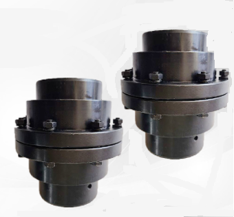 |
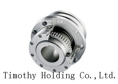
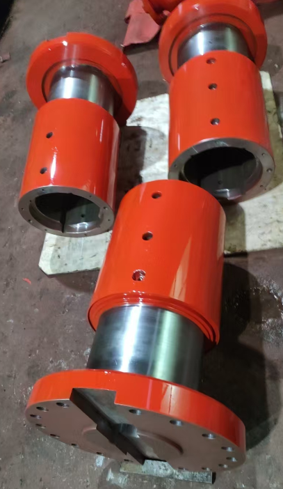
| drum gear coupling ,www.timothyholding.com |
https://www.timothyholding.com/Lubrication-Methods-for-Gear-Couplings.html


 .
.