Monday, June 9, 2025

The processing steps for drum gear couplings


The processing steps for drum gear couplings

文章附图

What are the processing steps for drum gear couplings ?
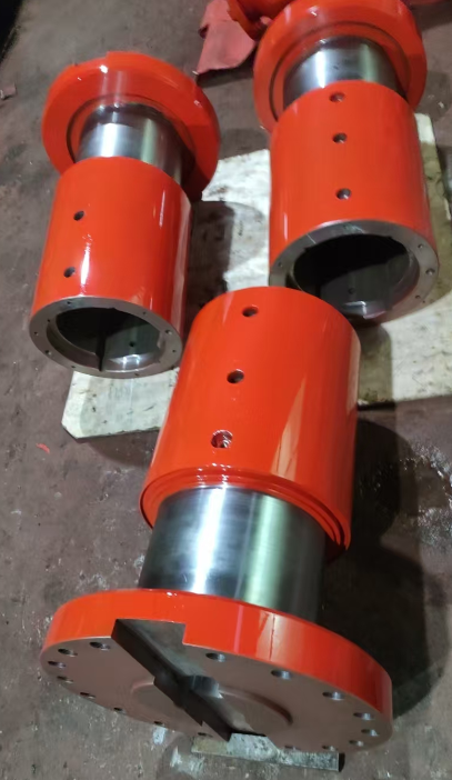
Drum gear couplings are generally processed through turning and milling operations (CNC milling ensures higher precision). Keyways can be machined via wire cutting or broaching.

Processing Methods:
Typical manufacturing steps include turning, milling, gear hobbing, and gear shaping. The tooth surfaces undergo high-frequency quenching. For higher performance requirements, die forging is used to shape the coupling before machining. Some couplings are formed using cast steel or cast iron, followed by machining.

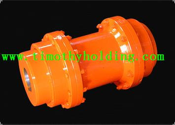
drum gear coupling for crane.png

Technical Overview:
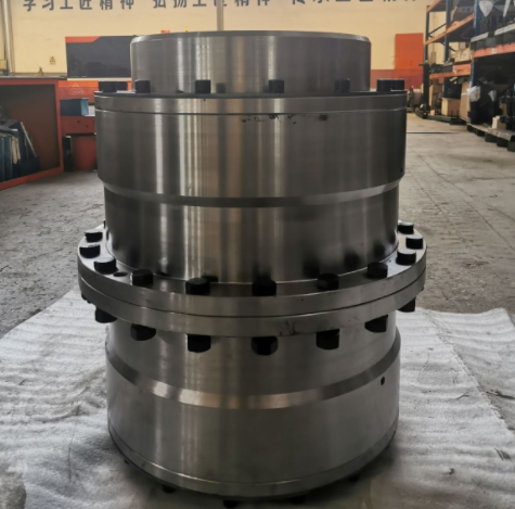
Drum gear couplings fall under the category of flexible-rigid couplings. They consist of internal gear rings and flanged half-couplings with external teeth. The external teeth are either straight or drum-shaped. Compared to straight-tooth couplings, drum-shaped teeth allow for greater angular displacement, improve tooth contact conditions, enhance torque transmission capacity, and extend service life.

Key Advantages:

1. High Load Capacity: The carburizing and quenching treatment of the drum-shaped tooth surfaces significantly increases load-bearing capacity.

2. Reduced Wear: When forced oil lubrication is applied, tooth surface wear decreases dramatically (to approximately 10% of that with grease lubrication). Circulating oil also dissipates heat generated by rolling mills and gear friction, preventing degradation of the material’s allowable contact stress.

3. Durability: Under normal conditions, tooth breakage is avoided, meeting the demands of continuous rolling mill operations.

4. Axial Flexibility: The design accommodates axial displacement during rolling mill operation, enabling easy expansion and contraction.

5. Operational Benefits: Safe, clean, and efficient performance.


https://www.timothyholding.com/The-processing-steps-for-drum-gear-couplings.html

Wednesday, June 4, 2025

Application and Considerations for Couplings in Rolling Mills


Application and Considerations for Couplings in Rolling Mills

Timothy Cardan Shafts
文章附图

Application and Considerations for Couplings in Rolling Mills

1. Application of Couplings in Rolling Mills

Couplings are critical transmissioncomponents in rolling mills, connecting the motor, reducer, and work rolls totransmit torque and accommodate misalignment. The most commonly used typesinclude:

  • Gear Couplings: Widely     adopted due to their high torque capacity (standardized for <1000 kN·m     in China) and ability to handle slight angular/radial deviations.

  • Elastic Sleeve Pin Couplings: Used in some mills for their compact size and heavy-load     capability, suitable for low-speed, high-torque applications. However,     they are being phased out and should be avoided in new designs.

    sleeves.png

2. Key Considerations

  • Axial Load Resistance: Gear     couplings in rolling mills often endure heavy axial loads, which may shear     the sealing end cover screws, damage seals (causing oil leaks), and     accelerate gear wear. Solution: Increase screw diameter in     heavy-duty designs.

  • Precision & Balancing: For high-speed applications (e.g., roll shafts), couplings must be     dynamically balanced to minimize vibration.

  • Obsolescence Risk: Avoid     outdated designs like elastic sleeve pin couplings unless necessary for     legacy systems.

3. System Integration

Rolling mills consist of a prime mover(motor), transmission (couplings, gearboxes), and actuators (rolls). Propercoupling selection ensures efficient power transfer, reduces downtime, andextends equipment life.

Note: Regular maintenance (e.g., lubrication, sealinspection) is essential to prevent failures in harsh rolling mill conditions.


Translation Rationale:

  • Structure: Organized     into clear sections for technical readability.

  • Terminology: Uses     industry-standard terms (e.g., "dynamic balancing,"     "angular/radial deviations").

  • Conciseness: Combines     related ideas (e.g., axial load effects + solutions) for efficiency.

  • Warnings: Explicitly     flags phased-out components to align with the original text’s intent.

https://www.timothyholding.com/Application-of-Couplings-in-Rolling-Mills.html

Maintenance Methods for Universal Joint Couplings


Maintenance Methods for Universal Joint Couplings

文章附图

Maintenance Methods for Universal Joint Couplings


Universal joint couplings are widely used in various industries including metallurgical machinery, heavy machinery, petroleum machinery, construction machinery, lifting and transportation equipment, railway vehicles, light industrial machinery, precision machinery, and control systems for transmitting torque in mechanical shaft systems.


Assembly Techniques:

1.Preparation:

oRemove all burrs and clean all components thoroughly before assembly.

2.Alignment:

oEnsure the bearing hole centerlines of the two intermediate welded yokes are on the same plane during assembly, with a maximum deviation not exceeding 1°.

oThe spline section should slide smoothly, and the joint should rotate freely.

3.Surface Treatment:

oClean all surfaces.

oApply anti-rust grease to the flange end faces and keyways.

oApply one coat of anti-rust primer to the remaining surfaces, followed by spray painting (brushing is not recommended).
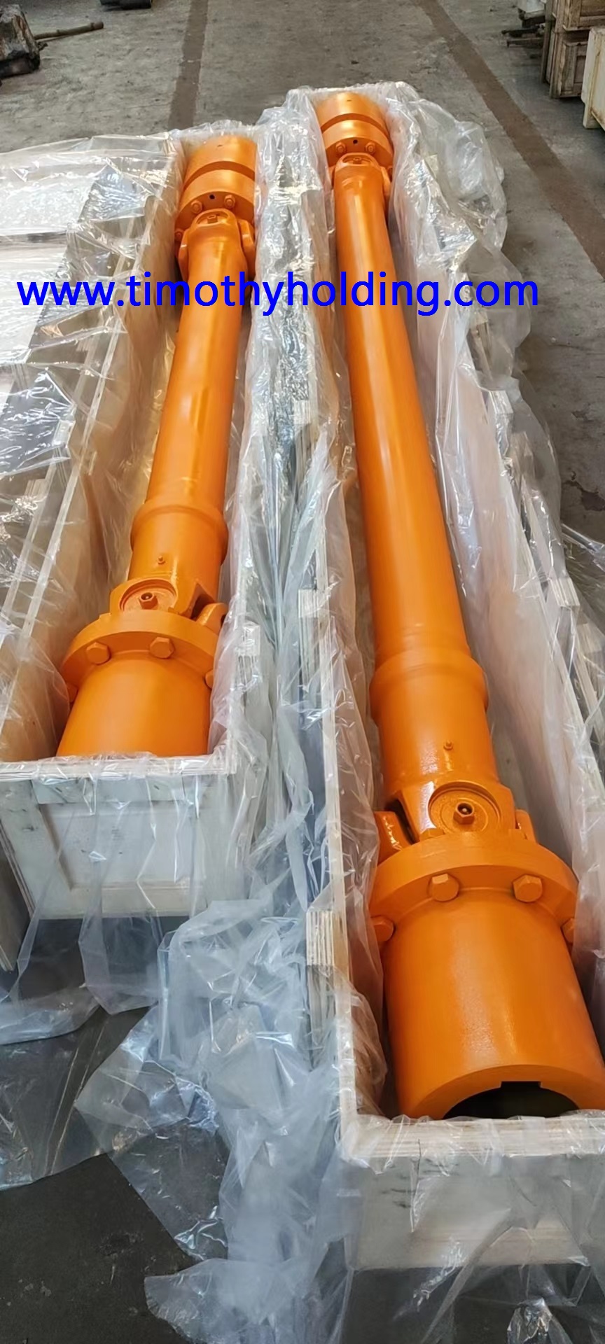
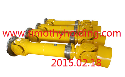
cardan shaft for rolling mill.jpg

Maintenance Methods:

1.Regular Lubrication:

oStandard conditions: Lubricate weekly.

oHigh-temperature conditions: Lubricate daily.

oUse recommended lubricants suitable for the operating environment.


2.Extended Service Life:

oRotate the cross shaft by 180° during each disassembly to ensure alternating use of the cross shaft journals, promoting even wear distribution.

Structural Varieties:

Universal joint couplings are available in multiple structural types, with the key features being:

•Large angular compensation capability

•Compact design

•High transmission efficiency


Common types include:

1.Cross Shaft Type (Most commonly used)

2.Ball Cage Type

3.Ball Fork Type

4.Lug Type

5.Ball Pin Type

6.Ball Joint Type

7.Ball Joint Plunger Type

8.Three-Pin Type

9.Three-Arm Type

10.Three-Ball Pin Type

11.Hinged Lever Type

Each type is categorized into heavy-duty, medium-duty, light-duty, and small-duty based on the torque transmission requirements.


Key Maintenance Points:

•Inspection Frequency: Monthly for standard applications, weekly for high-load or high-speed operations

•Lubricant Selection: Use high-temperature grease for elevated temperature environments

•Wear Monitoring: Check for play or backlash during routine maintenance

•Alignment Verification: Confirm proper alignment during seasonal maintenance

Proper maintenance following these guidelines will ensure optimal performance and extended service life of universal joint couplings in various industrial applications.


https://www.timothyholding.com/Maintenance-Methods-for-Universal-Joint-Couplings.html


Wednesday, May 21, 2025

Universal Joint Couplings as Critical Mechanical Transmission Components


Universal Joint Couplings as Critical Mechanical Transmission Components

来源:https://www.timothyholding.com作者:Timoghy Cardan Shaft网址:https://www.timothyholding.com/Universal-Joint-Couplings-Transmission-Components.html
文章附图

Universal Joint Couplings as Critical Mechanical Transmission Components

Fundamental Role in Power Transmission

Universal joint couplings serve asessential components in mechanical power transmission systems, widely employedin:

  • Automotive     systems

  • Lifting     and transportation equipment

  • Construction     machinery

  • Industrial     machinery

    Universal joint couplings.png

Common Types of Constant Velocity Joints

  1. Rzeppa (Ball-type) Joints

  2. Double Cardan Joints

  3. Cross-slider Couplings

  4. Disc-type Couplings

These are particularly suitable forconnecting:

  • Intersecting     shafts

  • Parallel     shafts

  • Providing     constant velocity transmission

Advanced Spatial Mechanism Applications

Recent research has developed specializeduniversal joint designs for:

  • Direct     connection of spatial intersecting shafts

  • Large-angle     intersecting shaft connections (with wide variable range)

  • Simplified     manufacturing with fewer components

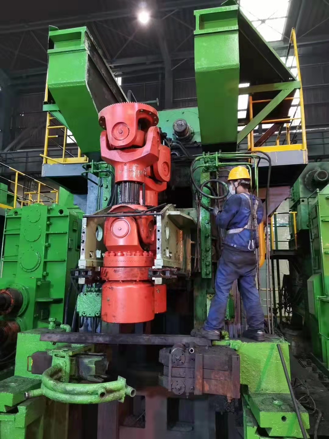
Critical Application Case: Tube RollingMills

In rolling mill main drive systemsconsisting of:

  • Main     motor

  • Reducer

  • Connecting     shaft

  • Universal     joint coupling

The universal joint coupling represents themost vulnerable mechanical component, where traditional design approaches facedlimitations:

Traditional Design Limitations

  1. Engineering Mechanics     Methods

    • Limited accuracy

    • Poor reliability

  2. Empirical Formula Methods

    • Based on experimental data

    • Required large safety factors

    • Resulted in oversizing and higher costs

Modern Computational Analysis Advancements

With computer technology development,numerical analysis methods have revolutionized design:

Finite Element Method (FEM) Advantages

  • Powerful     computational mathematics approach

  • Widely     adopted in metallurgical equipment design

  • Particularly     effective for complex components like universal joints

  • Provides     practical, reliable and convenient analysis

Modeling Optimization Techniques

Key simplifications in FEM modeling:

  1. Focus on Critical     Components

    • Primarily analyzing the yoke head

    • Simplified modeling of roll-end components

  2. Contact Simulation

    • Independent modeling of:

      • Yoke

      • Jaw

      • Roll-end flange

    • Creation of contact pairs to simulate force transmission

  3. Reasonable Simplifications

    • Ignoring non-load-bearing bolts

    • Omitting minor fillets and rounds

    • Eliminating rigid body displacement

Performance Enhancement Strategies

  1. Precision Manufacturing

    • Improved component geometry

    • Enhanced surface finishes

  2. Material Optimization

    • Advanced alloy selection

    • Heat treatment processes

  3. Maintenance Considerations

    • Lubrication system design

    • Wear monitoring techniques


https://www.timothyholding.com/Universal-Joint-Couplings-Transmission-Components.html

Sunday, May 4, 2025

Coupling Functions in Transmission Systems

 Coupling Functions in Transmission Systems

  1. Shaft Connection &     Torque Transmission

    • Flexible couplings with elastic elements compensate for axial,      radial, and angular misalignment.

  2. Overload Protection

    • Types: Pin-type, friction, magnetic particle, centrifugal,      hydraulic.

  3. Vibration Damping

    • Compensates for misalignment caused by machining errors,      load-induced deformation, and thermal effects.

High-Speed Grinding Applications 

  • Stiffness and power in     grinding systems are critical for high-speed operations.

  • High-speed spindle units are     key components in grinding machines.

  • Grinding     wheels require high strength and optimal abrasive performance.

  • Cooling systems are     essential for high-speed grinding efficiency.


Key Takeaways

  • Couplings     are vital for misalignment compensation and vibration     reduction.

  • Material     selection, forging precision, and heat treatment directly impact     performance.

  • Sealing     technology ensures longevity in harsh environments.

  • High-speed     applications demand rigid yet flexible coupling solutions.

  • https://www.timothyholding.com/Coupling-Functions-in-Transmission-Systems.html

cardan shafts with couplings

 cardan shafts with couplings for steel industry equipment


Material:35CrMo and 20CrMnTi

Timothy Holding Co., Ltd.was founded in 1993. It has been specialized in producing universal joint shafts (also called cardan shaft   or universal spindle) for more than twenty years. Our products are largely used in rolling mills,Pipe straighteners,Steel mill,tube mill,Continuous casting machinery,Paper machines ,Piercing mills,Bridge cranes,Steckel mill,Punchers,Roller conveyor, Rotating furnace,Mining machinery , Metallurgical Machinery ,big pumps and other heavy duty machinery .


cardan shaft

https://www.timothyholding.com/cardan-shafts-with-couplings.html


steel industry equipment.jpg
cardan shaft in steel factory

Nuclear Power Plant

Puncher

Steekle mill

Straightening machine

Contact Name:August

Mobile Phone:+86-13758897904

E :august@timothyholding.com

Web:www.timothyholding.com

Address:55# Jinshi Road ,Lecheng Industrial Park,Yueqing City,Zhejiang Province,China

Thursday, January 23, 2025

SWC225BF Cardan Shaft


SWC225BF Cardan Shaft

SWC225BF Cardan Shaft


Material:35CrMo and 20CrMnTi


Largely used in rolling mills,Pipe straighteners,Steel mill,tube mill,Continuous casting machinery,Paper machines ,Piercing mills,Bridge cranes,Steckel mill,Punchers,Roller conveyor, Rotating furnace,Mining machinery and other heavy duty machinery .


Contact Name:August

Mobile Phone:+86-13758897904

E :august@timothyholding.com

Web:www.timothyholding.com

Address:55# Jinshi Road ,Lecheng Industrial Park,Yueqing City,Zhejiang provice,China